This post is about making my Anet A8 Plus into an multi-purpose 3D printer that can engrave with laser.
Before I start the post, I was able to do all of this work thanks to an user named vandenmar who posted about laser engraving on prusa MK3.
If you use different type of printer, better check out his post.
Step 1. Materials
In order to laser engrave, of course I need an laser module.

The one I bought is an Eleksmaker's LA03-3500 with 3500mw power and has an TTL control.
Then, I prepared an Arduino Uno R3 board, Small breadboard, some resistors, cadmium sulfide cell(CdS), LED, and some wires to control the TTL signal with the cooling fan power.
Step 2. Mounting the Laser
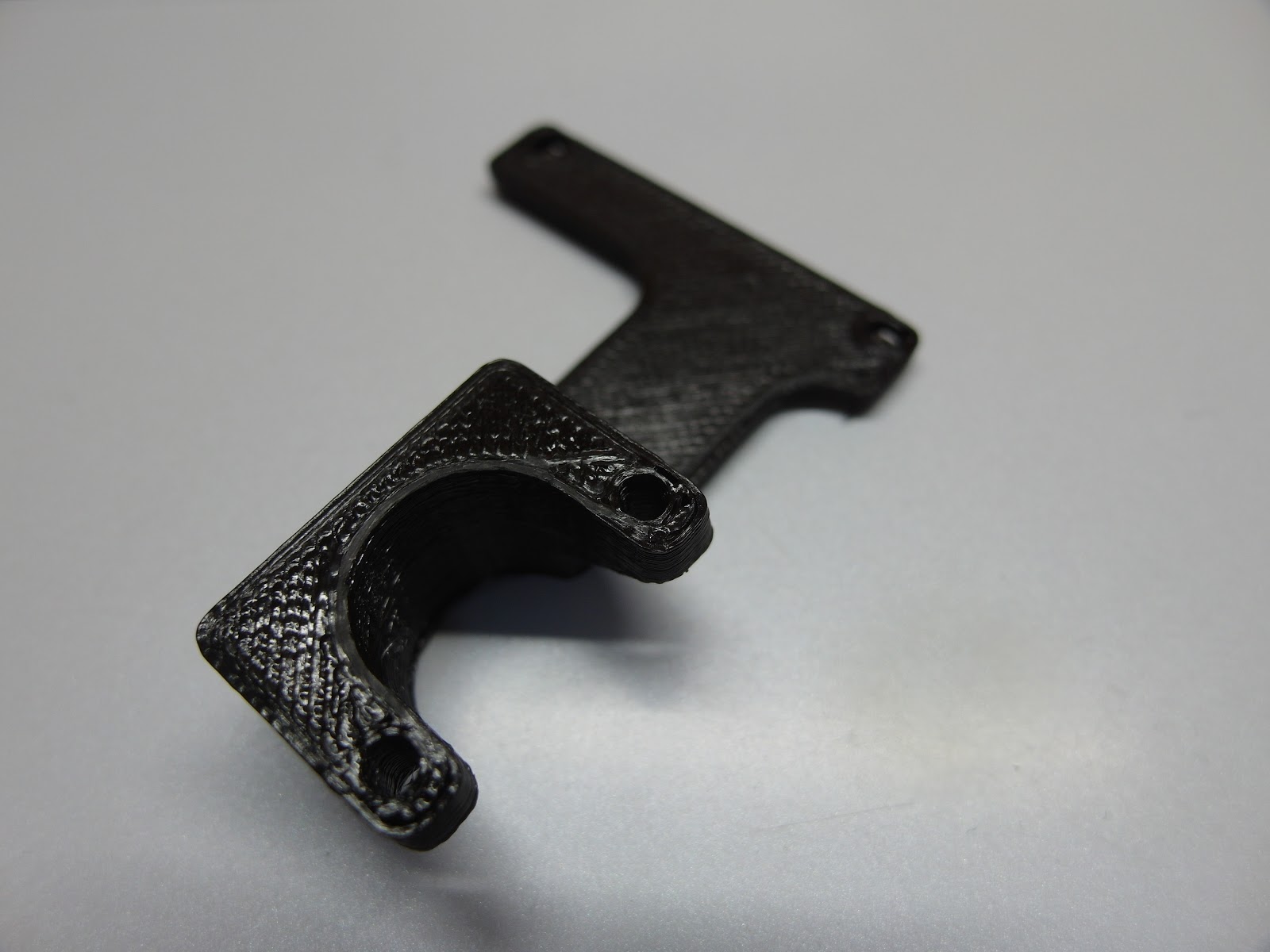
In order to use the laser, I need to mount it somewhere in the extruder parts. So I decided to design a Laser Mount that uses the 4xM4 screws placed in the extruder holder.(It uses the screw that is already in the printer, don't need to buy M4)

In this way, the laser mount will be hold tight, even when the printer head moves quickly getting a lot of acceleration.


[Sketch of Mount]

[Modeling With SolidWorks]

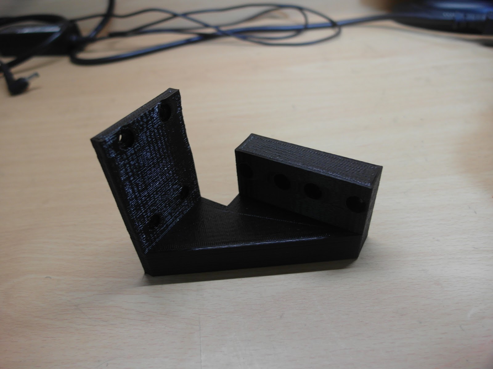
[Printed Mount]
This version of laser mount is an advanced version of the one, that I made before.
It can hold the laser module, TTL controller, Arduino Uno R3 with M3 screws. And It is more stable than before.
Also It is compatable with all LA series laser of Eleksmaker
It can hold the laser module, TTL controller, Arduino Uno R3 with M3 screws. And It is more stable than before.
Also It is compatable with all LA series laser of Eleksmaker
Here is the link of this mount : https://www.thingiverse.com/thing:3624983
Now, we need to assemble the modules, board to this mount.


[Diagram of Assembly]

[Assembly of Arduino Uno R3]

[Assembly of Laser Moudle/TTL Controller]

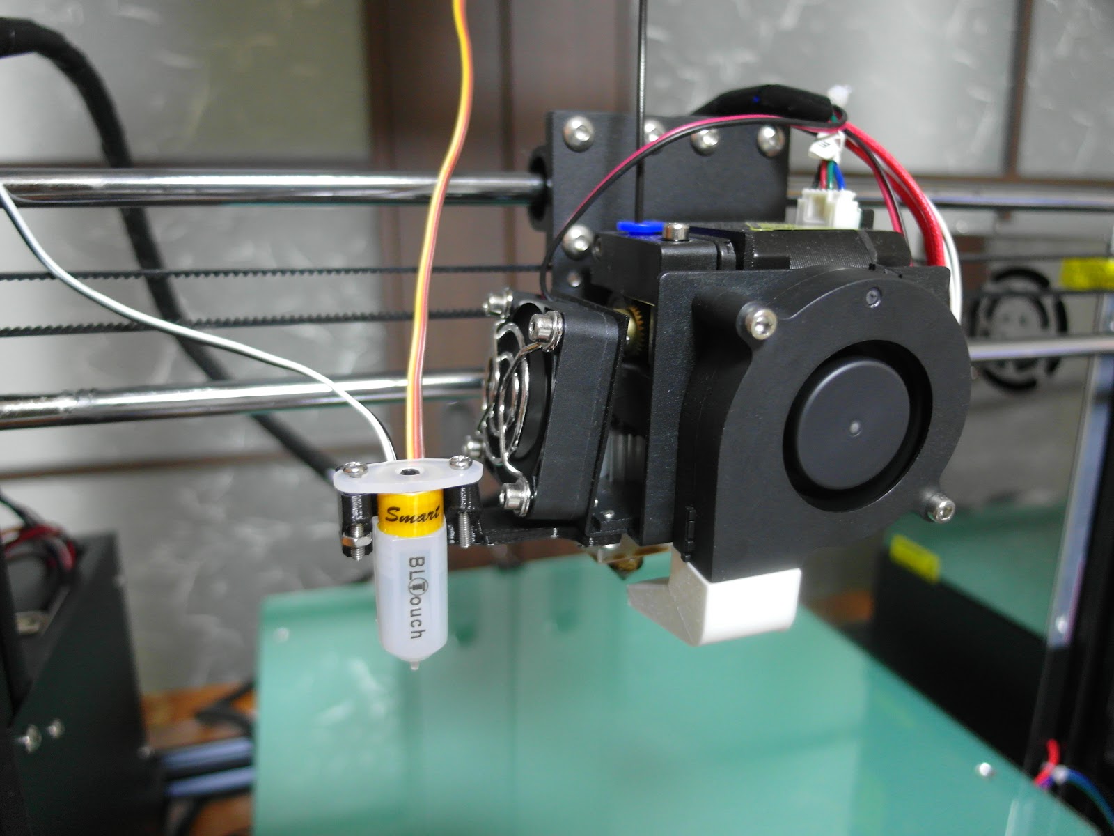
[Assembly of Mount to Printer-M4 Screw]
Now the assembly is done, and wiring is left.Step 3. Wiring Cooling Fan's Power Line to Arduino
I will use the power signal of the cooling fan, to control the TTL signal. So I need to wire the cooling fan's power line to an LED, that will give a signal to the arduino.
Anet's cooling fan voltage is 24V so I need to regulate it to about 5V.
(At the first, I tried to wire the cooling fan's signal directly to the TTL signal port, regulating it to 5V, but it didn't work properly. Don't know the exact reason, but TTL signal read the frequency of the input voltage so I used the arduino to produce 5V signal for TTL)
(At the first, I tried to wire the cooling fan's signal directly to the TTL signal port, regulating it to 5V, but it didn't work properly. Don't know the exact reason, but TTL signal read the frequency of the input voltage so I used the arduino to produce 5V signal for TTL)
This regulating can be done very easily with 24V-5V regulator Module but, the one I ordered in banggood didn't arrived so I used 3 resistor to make 5V.
So now, the 24V is successfully changed to 5V, so I connected an LED. And the LED is going to turn on/off by the cooling fan's signal.
(Also, I added an switch to change the cooling fan mode. Normal status, the power goes to the cooling fan, and when I switch, the power goes to the LED)
Then I connected an CdS cell to read the LED's light signal. And then connect the CdS cell to the Arduino to read the signal.
Then I need to wire the OUTPUT Signal of the Arduino to the TTL port of the Laser. This way the arduino can read the CdS signal, and send 5V signal to the TTL module.
Then I need to wire the OUTPUT Signal of the Arduino to the TTL port of the Laser. This way the arduino can read the CdS signal, and send 5V signal to the TTL module.

[Complete Diagram of Wiring]

[Picture of Wiring]
So It is going to be like this
Cooling fan on -> LED on -> CdS resistant LOW -> 5V to TTL
Cooling fan off -> LED off -> CdS resistant HIGH -> 0V to TTL
Step 4. Programming Arduino for TTL Control
The wiring is done, and I need to program the arduino to send signals to the TTL.
Program code is almost same with the example code with CdS sensor.
This is the code, I made
int laz = 9;
int cds = A0;
void setup(){
pinMode(laz,OUTPUT);
pinMode(cds,INPUT);
Serial.begin(9600);
}
void loop(){
int num = analogRead(cds);
Serial.println(num);
if(num<100)
{
digitalWrite(laz,HIGH);
}
else{
digitalWrite(laz,LOW);
}
delay(50);
}
I used digital pin 9 to Send signal to the TTL module, and used analog pin 0 to read signal from the CdS cell.
So if the reading value of the CdS, is below 100, the TTL signal is on. (CdS signals 20~30 when LED is full bright, signals 255 when LED is off).
Now, the programming is complete and, I uploaded this to the arduino and tested it using Gcode command.
M106 S255 will trigger the LED, and M107(or M106 S0) will turn of the LED.


[Relation between LED, LASER]
[Testing with Gcode command]
As like the testing video, it was a success.
Now all left is to engrave some images.
Step 5. Preparing Files to Engrave
To Engrave, we need to have an svg file(vector type). Rather we can get a vector file directly or we can make an covert an raster type to vector with Adobe Illustrator.
If you got an raster image, then use 'image trace' in Adobe Illustrator to change it into black/white picture. Then save it in svg type file.

[Image Tracing]
Step 6. Engrave using Software
Whether you got an vector file directly or converted an raster, the next step is to convert vector to Gcode that printer can move.
The program that I use is 'Laribo'.
It is made by the user named vandenmar that I mentioned at the starting of this post.
Links again : https://www.instructables.com/id/Laser-Engraving-on-Your-Prusa-MK3/
This program converts the vector line into Gcode, that the printer can move, and also the most important thing is, it gives M106 S255 command in the engraving line, and while moving outside the line it gives M107 command to turn off the laser.

[Converting svg to gcode with Laribo]
We can control the engraving speed, moving speed, Laser position height, and curve resolution. High Curve resolution gives more detail but, it takes more time, and it slows the speed in curves, so the laser might burn too deep.
So I recommend to use low value.
After saving, all left is engraving.
When engraving, you need to calibrate your focus of laser by the height.(Laser Height - height of engraving thing)
Then, you need to position the plate you wanna engrave.
After that, Just enjoy the laser show.
(Must use your safety goggles. Safety is first than fun)
[Engraving Video - https://www.youtube.com/watch?v=8FXSLyOCcWE ]

[Engraved Wood Plate]
Thank you for reading this post. See ya next time~
Bonus Engraved Photo


